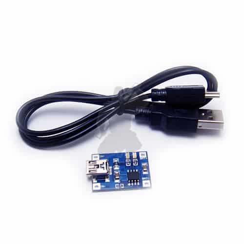
Mini USB Lithium Battery Charging Board
£1.78 Inc VAT
Charge any lithium battery by USB with up to 1a charging current. To lower the charging current simply change a resistor on the board to lower the current.
In stock

This USB charger pcb is an extremely small module measuring in at only 19mm x 25mm. It uses the TP4056 controller and is setup as default to charge at a 1A charge current.
The board runs on any 5 volt power supply, this can be through the usb connector or there are solder pads if you want to use your own connector / adapter. You need to make sure that the 5v supply whether usb or from an adapter is rated at least at a 1000ma output.
If using with smaller batteries, 14500, 18350 etc you will need to change the charge current from 1000ma to something more suitable. Most entry level lithium battery chargers such as Trustfire and Ultrafire charge at 500ma so consider that a suitable level if you’re not sure what to change it to.
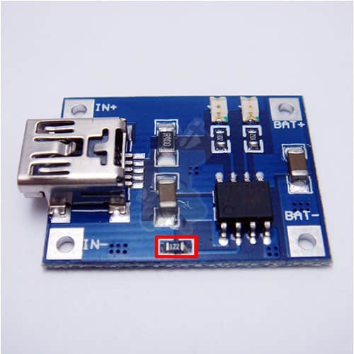
The resistor is a 0603 size smd resistor and are quite small so take care with your soldering if replacing. The resistor you need to swap to change the charge current is outlined in red in the second product image.
| Resistor SMD 0603 | Charging Current |
|---|---|
| 30k | 50mA |
| 20k | 70mA |
| 10k | 130mA |
| 5k | 250mA |
| 4k | 300mA |
| 3k | 400mA |
| 2k | 580mA |
| 1.66k | 690mA |
| 1.5k | 780mA |
| 1.33k | 900mA |
| 1.2k | 1000mA |
Supplied with usb cable
Please note if you get the battery polarity wrong it will release the magic blue smoke that makes the charger work.
| Weight | 0.010 kg |
|---|---|
| Dimensions | 2 × 2 × 1 cm |


